what is microhacking?

Most circuitbending and hacking involves perverting a complete circuit. Microhacking is a simple (and possibly cheesy) term I'll be using for taking individual electronic components or concepts and giving them new uses.


ATTENTION: this blog focuses on creative misuse of electronics so be careful and note that I am not responsible for anything.

Wednesday, October 22, 2008

World's Worst Microphone

Tilt Switches
Tilting here, tilting there, turning it on, turning it off... Okay tilt switches are boring.


It is a microphone?
Sure. An audio signal is just a fluctuating voltage. The reverse is often true; many varying voltage signals can treated as audio signal and be listened to. To use a tilt switch as an audio source you set it up to switch a voltage on and off and tilt away.


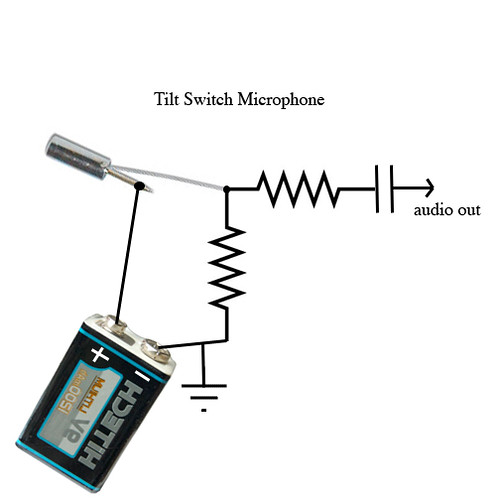
The resistor values are somewhat flexible. Start by trying 10k or 100k ohms for the resistor to ground and 1k for the other resistor. You can leave out the cap if you want a DC signal for control voltage use with a synth. Also make sure to use cheapo ball-in-a-can tilt switches instead of the mercury kind.


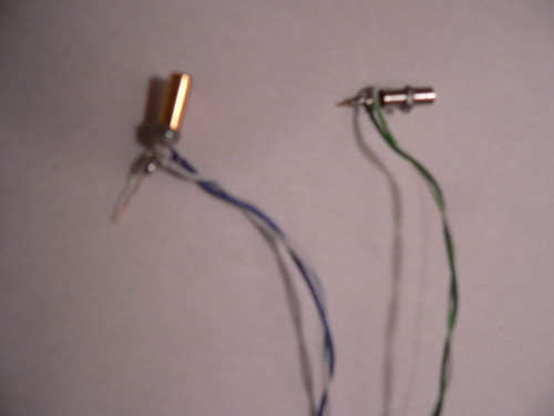
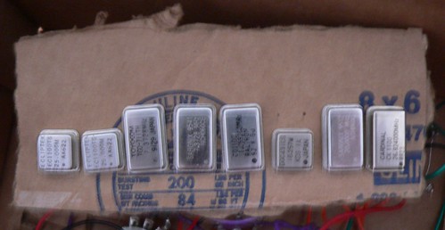
Above are part two quickly assembled "microphones." You may notice the needly spike on the right microphone and the uncut lead on the left one. I've found this can sometimes make mounting them easier. Which leads us to....

This is even shittier than I thought.

You knew there were going to at least a few quirks with this right? First off, it is more or less a contact microphone so you need to attach it directly to what you want to amplify. Also, the tilt switch only really reacts to vibrations from certain angles; the vibrations need to cause the ball-in-a-can to bounce in order to get an output that vaguely resembles what you want.

The best way to demonstrate the horrible nature of this microphone is to attempt to record some virtuosic guitar leads. The first three sound clips do just that. Chords first, then high notes, then low notes. The tilt switch was taped to the bridge of an acoustic guitar for the recording.

Earlier I mentioned that I leave one lead of the switch unclipped. This gave me the idea to use that lead as a needle for a record player. The records I have handy are scratched to shit but as these microphones turn everything into indistinguishable crunch, crackles, and pops I don't think it is too important. If you can't imagine a piano buried a mile under the crunch of the fourth clip, let's blame it on the scratched up record.


If you like getting carried away...

You don't even need to use a tilt switch to make a horrible microphone. I've had some fun replacing the tilt switch in this circuit with two pieces of tinfoil or a pie tin with a needle or slip of tinfoil on it. Any two conductive materials with the ability to jitter or bounce should work. There is a handful of homemade tilt switch articles online too.


Wednesday, October 1, 2008

Crystal Oscillators

What is a crystal oscillator?
Accord to wikipedia, "A crystal oscillator is an electronic circuit that uses the mechanical resonance of a vibrating crystal of piezoelectric material to create an electrical signal with a very precise frequency."


What
is a crystal oscillator intended to do?
Crystal oscillators provide a steady unchanging frequency. Originally they were used for stabilizing high frequency circuits such as radio transmitters or sonar, but today they are most commonly used for clocking digital circuits/computers.

How do I find one?
What are their secrets?
Crystal oscillators come in mysterious little metal boxes about the same size as your typical integrated circuit. It is best to buy them in assorted bundles. Not only is it cheaper (sometimes the cost ends being under 25 cents per oscillator), but you also get assorted frequencies. I've come across frequencies ranging from 4 Mhz to over 200 Mhz. This means the lowest frequency oscillator is actually over 200 times higher than the upper end of human hearing! Oh, they look like this by the way...


What can we do with them?
Many things! So many that I will probably keep coming back to write about these little lovelies again and again. The easiest way for us to use these is to exploit a phenomenon called heterodyning. Wikipedia says... "heterodyning is the generation of new frequencies by mixing, or multiplying, two oscillating waveforms." Heterodyning allows us to create audible tones from the supersonic frequencies generated by the oscillators. The theremin actually uses a heterodyning technique to generate sound too. The theremin has two supersonic frequencies one at a set frequency and one which changes frequency according to the proximity of your hand (inductance, capacitance, and magic are all involved). The tone you hear is the difference between the two higher frequencies. Since our crystal oscillators are always at a set frequency, different sounds are achieved by changing the amplitude levels of the oscillators or adding/subtracting new oscillators. First, lets get a steady sound....


WARNING: crystal oscillators expect a supply voltage of 5V. I have been powering these with a 9V battery. I have let the circuit sit powered for hours and nothing blew up or got smokey, but as crystals are made by approximately 97657 different manufacturers I cannot guarantee you will have the same experience. Whenever you are hacking anything please follow all the safety guidelines outlined in Nic Collins' book Handmade Electronic Music - The Art of Hardware Hacking.


Now that that is out of the way... you can see how easy the circuit is. You will probably want to use more than three crystals and you will definitely want a means to control them. The easiest control is to have an on-off switch for some of the oscillators. You can do this by using a SPST switch to disconnect the crystal from ground. A variable resistor between the power supply and the power pins on the crystals lowers the current available to the crystals and makes them "fight" for power. The crystals can also be mixed together through (variable) resistors. Throw some diodes in series with the output of each crystal for some dirtier sounds. Have fun and go crazy. Also note that a DC blocking capacitor isn't a bad idea.


Above is my friend's rendition of this circuit. It has a variable resistor in series with the power and a DIP-switch that can turn each crystal on and off. His box has no other components besides what is mounted on the front: no resistors, capacitors, diodes, etc. Below is a prototype I blindly put together after I tested things out a little bit and knew it would definitely produce sound. I don't recommend using many controls like I first tried doing. The circuit can drift and shift a bit without you flipping switches or turning knobs so limiting your controls can be useful.


Here are some sample sounds to demonstrate what you can do with this basic circuit. Yes, it is pretty much a one trick pony at this stage. Later I'll follow up with some articles on more complex uses such as interfacing crystals with CMOS circuits and control voltage generation for modular synthesizers.